Tool Vending Machine

Quick Overview
My team and I designed an Arduino controlled tool sorter/retriever.
-
Used SolidWorks to design a device that moves a grabber mechanism to a specified location in the X-Y plane using three stepper motors. Each stepper motor controlled a belt and pulley system attached to a guide rod while a grabber mechanism with an electromagnet at the end actuated a guide rod in the Z axis using a fishing line connected to a pulley.
-
Programmed an esp32 microcontroller running Arduino to implement the movement.
-
Manufactured the device using 8020 extrusions and FDM printed parts to construct the prototype.
-
Utilized a 3d laser cutter to create a wooden tool tray, assembled using box joints.
Introduction
I collaborated on a four-man team to design an Arduino controlled tool sorter/retriever. This device moves a grabber mechanism to a specified location in the X-Y plane using two A4988 stepper motors. Each stepper motor controlled an belt and pulley system attached to a guide rod. The grabber mechanism was controlled by another stepper motor the moved a guide rod in the Z axis using a fishing line connected to a pulley. An electromagnet attached to the end of the guide rod picks up the tools. This guide rod is constrained in the X-Y to maintain the orientation of the tools. Everything is controlled using an esp32 microcontroller running Arduino. We used a 15W powersupply and a MOSFET circuit with back EMF protection.
I utilized Solidworks to model and optimize the parts as well as model the XYZ movement. I used an Ultimaker to slice and print out parts for prototyping. I also utilized a 3d lasercutter to laser cut wood for the box-joint assembled tray holding the tool. We also showcased our project in a design showcase and wrote a technical report for the project.
Concept and Initial Computer Aided Design (CAD)
As mechanical engineers, my group and I are constantly misplacing our tools whenever we are working on our own projects. Each time we use a tool, we put it down close for further use, and then whenever we turn to reuse the tool, it's suddenly gone. To solve this problem, we thought what if we had a tool sorting machine that would give us the correct tool when asked for it and then put that tool back to it's original place when not in use. The device would be close to our workspace so we wouldn't have to go on a scavenger hunt each time we needed to fasten something.

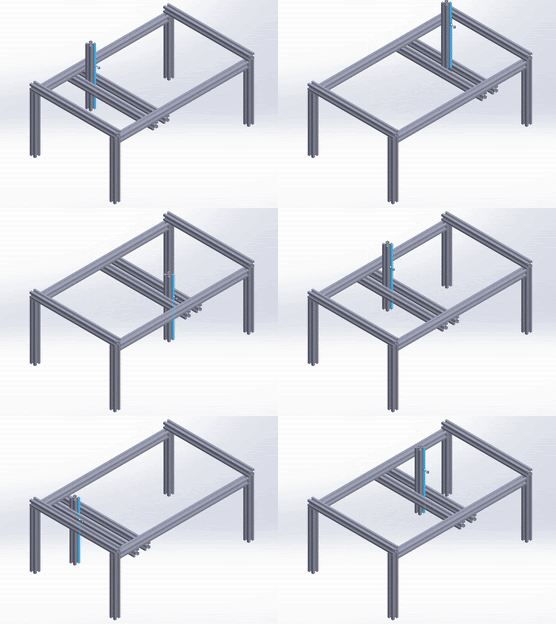
Fig. 1 Motion Concept
Fig. 1 shows our original concept of how we envisioned the machine to work. Mounted on a frame of t-slot extrusions, we would create a something capable of actuating arms in the X-Y-Z plane with some sort of grabber mechanism at the very end to pick up and put down tools.

Fig. 2 Version 1 Design Prototype
Our first iteration uses three separate stepper motors, each controlling the X-Y-Z motion of the grabber using guide rods and belt driven pulleys. The X and Y plane guide rods utilize the center block as a connection point, which is clamped onto both belts. As one stepper motor drives a belt, it pulls the center block along with the other guide rod system to a new location. The Z axis stepper motor then moves grabber mechanism up an down.


Fig. 3 Center Block Different Iterations
We were initially going to use a guided belt and pulley system like the guide rods we used to actuate our X-Y plane motion, before settling on using a pulley with a fishing line to pull up the grabber and then letting gravity move the grabber down. We made the grabber and the center block interface square to prevent the tool from rotating during transport. Since most of the tools are made with some type of ferromagnetic steel, we decided to use an electromagnet as the actual grabber.
Final Design

Fig. 3 Final CAD of the frame


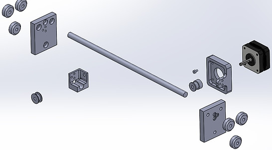
Fig. 4 Center Block Final Design and Exploded View

Fig. 5 Guide Rod Block Assembly Exploded View
Fig. 3 - 5 depicts the final CAD of the frame, center block, and guide rod assembly. The only real change between this design and the previous one was that we realized that we didn't need the entire grabber arm to be square, only a small part of it to preserve the anti rotational aspect and then we could save material by making it the same circumferential dimension as the electromagnet.
Manufacturing
Frame and Center Block


Fig. 6 Assembling the frame
Fig. 6 depicts us trying to get all the t extrusions into place.


Fig. 7 Drill Guide
One of the issues that we ran into was that our brackets for each guide rod kept moving out of sync and need a stiffer mounting method. To solve this, instead of clamping the guide rods in place, we tapped the center of the rod using a 3d printed drilling jig.

Fig. 8 Center Block
Fig. 8 depicts our 3d Printed center block including all of the wiring to the stepper motor and our electromagnet. Another issue we ran into was that our stepper motor kept missing the exact number of steps to keep our fishing line constantly under tension and as a result, the fishing line would fall off the pulley when reaching the very top or bottom of the movement. To solve this, we just cut a piece of cardboard to make the fishing line harder to escape the pulley.
ToolBox Tray


Fig. 9 Toolbox Tray CAD and exploded view


Fig. 10 Manufacturing the tray

Fig. 9 - 10 depicts a toolbox tray that we laser cut out of wood and put together using box joints. During manufacturing, we also realized that our electromagnet and center block did not have enough reach for the bottom of our frame, and since we did not have access to a bandsaw at the time, we decided to print some height adjusters that would clamp onto the T-extrusions
Fig. 11 Tray Height Adjuster
Electrical and Coding

Fig. 12 Wiring
Fig 12 depicts our entire electrical setup using ESP32 to run 3 A4988 stepper drivers to move 3 motors. We also included a mosfet circuit to protect against back emf. This helps our electromagnet when it heats up during use. To power everything, we used a 15V DC power supply, which allows us to draw 3.5V using a 25% duty cycle. We also calculated our Maximum acceleration for a 1 pound tool to be 3484 steps/s^2 before reaching our stall torque. This allows us to use a minimum current draw.
Coding

Fig. 13 Toolbox Coordinate System
Fig. 13 depicts the coordinate system we used based on our toolbox for our code. Our code basis is as follows:
Input
while(Serial.available() == 0){ }
Serial.readStringUntil(‘\n’)
if & else to make sure that the use input is valid
charAt(0) to convert String to char
switch & case for assign X & Y coordinates based on user input
Output
Calculate the number of turns to reach X & Y coordinates
Turn on X & Y motors (CW)
CW in Z axis, turn on the electromagnet, then CCW in Z
X & Y motors operate in CCW back to Home Position
CW in Z axis, turn off the electromagnet, then CCW in Z
Final Product and Video Demo


