SIHENG JAMES YANG
3lb Combat Robot
I created a 3lb combat robot in order to fight other 3lb robots

Quick Overview
I designed a cradle-to-grave 3lb battle bot. The constraints were a 3lb competition weight and a $500 budget.
-
Determined design requirements from previous winning robots such as weapon shape drive assembly and weapon assembly designs, materials choices, and structural designs. I looked at common impact damages and material failures seen during competition. I researched weapon rotational energy and rpm, drive maneuverability capabilities, and understanding what optimized each robot.
-
Optimized a weapon shape based on a required reach and mass, and calculated a motor, gear ratio, and battery specification capable of achieving the required rotational speed based on the weapon rotational inertia.
-
Used SolidWorks to design a vehicle structure and internal component layout and reiterated design based on SolidWorks analysis tools for weight distribution and total weight reduction, and 3D prototype testing. Selected 6061-T6 aluminum and Ultra High Molecular Density Polyethylene (UHMWPE) for the structure, TPU printed internal mounts and 4140 steel for the weapon. Prioritized ease of assembly (DFA) in the design to facilitate a quicker repair time between matches. Reinforced the structure by placing alloy steel rods within the UHMW walls.
-
Used ANSYS Explicit Dynamics to evaluate weapon impact stresses. Modified the weapon design to include needle roller bearings and thickness adjustments to relieve stress concentrations by 10%. Used impact analysis to balance weapon rotation after manufacture.
-
Used an OMAX waterjet and laser cutter to manufacture the UHMW structural components and the 4140 weapon. Used a lathe and cobalt drill bits to drill and tap hardened steel and a torch for heat fitting bearings Used an Ender 3 to print out the TPU motor mounts.
-
Soldered all the electrical components together. Reinforced PCB’s with hot glue.
As a result, I created a strong, lightweight, robot that is easy to manufacture and assemble, capable of maneuvering 5 m/s while delivering 88J of weapon energy spinning at 16000 RPM. The total weight of the robot is 2.95 lbs and an end cost of $515.68 with a unit price of $473.62.
Initial Concept
I started this project with another fellow engineering student, Harin Jeong, when he encouraged me to join Robobears at UC Berkeley, which is the Combat Robotics Club there, and after watching our friend Anthony Moody compete on the TV show Battlebots on Discovery. We started by examining what design elements gave an edge to robots that won competitions such as at National Havoc Robot League (NHRL) or on Battlebots. We looked at weapons shapes, motor, esc, and battery specifications and materials used. We examined structural design and material optimizations such as what sort of trusses where used, how ribs were placed, what were the engineering considerations and mechanical principles that encouraged such and such designs. In terms of materials, we examined what components were beefed up on winning robots and where weight was saved with minimal effect on effectiveness. Based on our research, we found that vertical spinning weapons have had a lot of success due to fact that after the initial impact, an opponent robot would be launched into the ceiling of the arena, followed by gravity slamming our opponent into the ground, allowing us three separate impacts for the price of one. Our initial design was a three pronged A2 tool steel weapon mounted on 6061-T6 aluminum (Fig. 1).
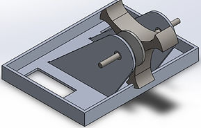


Fig. 1 Initial Planning and CAD Design
Following this design and after getting design critique from others, we changed our weapon to an egg beater design (Fig. 2), which is a vertical spinner with an exposed weapon shaft. This type of design gives a number of advantages over our initial design. This allows a better weight distribution along the outside of the weapon. For the same amount of weight, we now can get a larger rotational inertia resulting in more impact energy as well as more impact surface area. The exposed shaft is a non issue due to the fact that the weapon would be rotating incredibly fast. This negates the possibility of damage to the shaft from an opponent's weapon. On the other hand, if our weapon is no longer rotating, then the match is already lost, rendering the entire thing moot.
We also realized that since our pulley belt would be within the same space as the weapon, it would be better to use a dead-shaft design. i.e. non rotating shaft where the bearings would be located on the weapon itself rather than the mounts.

Fig. 2 Egg Beater Weapon
Internal Component Selection
In order to determine our our structural design, we need to choose our internal components such as our drivetrain motors, weapon motors, battery size, receiver and esc's since these are components that we are unable to manufacture ourselves. A well balanced robot will not only have a weapon capable of delivering a large amount of energy, but also a structural design capable of taking a large amount of hits, and a drivetrain with good maneuverability. A good weight ratio to aim for 1lb for the weapon system, 1lb for the drive system, and then the rest to be used for structure and battery.
Motors
For the weapon, a powerful motor with high torque is needed to generate the necessary spinning force for the eggbeater spinner. A brushless motor with a high RPM rating and low internal resistance is a good choice for this purpose due to the lack of mechanical brushes. This will also be advantageous since we will be using timing belts, so when the weapon impacts, there won't be as much of a buildup of back driven emf due to the impact. For the drivetrain, a motor with high torque and good speed control is important. A gear motor with a high gear ratio is a good choice for a beetleweight robot, as it provides good torque and speed control in a compact size.
Based on what motors are used in past winning robots that employ a beater bar design, our weapon motor will be a S2838-2970KV. This motor has a good KV rating that should deliver a very high no load rpm depending on the voltage of our battery. For our drivetrain motor, to minimize shipping cost as well as motor cost, we will go with the 22mm 730rpm Planetary Gearmotor that is also offered on the same site.
To accompany these two choice will be the MB30020 20A BLDC esc for the weapon motor and a Fingertech tinyESC v2 for the drivetrain. Both have a high enough current rating to handle these motors. As an addendum, Fingertech now sells brushless wheel motors, which weren't available at the time. The next version of this robot will use those instead.
Battery
For our weight class, the most common battery used are either 2s or 3s Lithium Polymer (LiPo) batteries due the high energy density, low weight, and high current deliverance. This is important for combat robots that need to produce high torque and power for their motors and weapons. LiPo batteries have a low internal resistance, which allows them to deliver high currents without significant voltage drop. They are also readily available. To find our battery requirements, we will use a nominal voltage of 11.5V with a 20A current as rated by the weapon esc and 2A current as rated by the wheels. Each match is 3 minutes.

However, our club has provide free batteries, with the maximum rated at 850mAh. Since we won't be moving the entire time, this would be acceptable battery capacity.
Materials
Our material selection will be optimized for weight to strength ratio, cost, availability, and machineability. Most of our stock material will be purchased from McMaster-Carr so that will be the basis of availability. This will limit our choices to 6061-T6 aluminum or Ultra high molecular density polyethylene (UHMWPE) for our structure and 4140 steel for our weapon.
First Iteration


Fig. 3 First complete robot
This is the first interation of a fully fleshed out robot. Most of the structure is constructed out of 1/8 or .1/4 inch 6061-T6 aluminum with UHMW covering and foam wheels. This design features invertible ears as a part of the weapon mounts in order to drive upside. Each wall is also bent on the top and bottom in a l-bracket fashion so that material stiffness is still maintained during hits. However most of this version was grossly overweight by over 1/2 lbs even after cutting out trusses in the material. At the same time, we discovered that some of the aluminum components would be unmanufacturable due to a lack of the proper bending die and acetylene torch to heat treat the aluminum during bending.
Next Few Iterations


Fig. 4 Versions 3-6
The next few Iterations of our design (Fig. 4), we swapped out various materials such as replacing our aluminum structure with a UHMW structure to save weight. We played around with different configurations of 3d printed mounts for the battery and motors with the idea of inserting metal rods throughout the chassis to reinforce the 3d printed mounts. Initially we were planning on threading aluminum rods to do this, but changed our minds after feedback to steel rods instead. we went through different iterations from a fully steel weapon to aluminum weapon with steel bars acting as teeth, until we finally settled on a fully steel weapon shaped like a ring. These changes were due to a series of feedback back and forth with people with much more manufacturing and machining experience than us. We finally changed our weapon design to be easily waterjet cut-able without the need for any finishing machining such as adding chamfers or fillets which would have required specialty drill bits to do such as cobalt, hss or carbide. We also changed our pulley ratio for our weapon 1:2 to get more torque.
Prototyping


Fig. 5 Prototyping
This is our prototype in order to check out wire spacing and to get a general feel for how strong using 3/16 inch steels rods within the plastic would be. Everything in blue is 3d printed out of PLA on an Ender 3 Pro. In order to reduce weight, we wanted to see if we could decrease the space needed for wiring and to see if everything would still fit. This would also bring the added bonus of putting our center of mass closer to the drivetrain in order to gain more traction with our wheels.
Changes:
-
We shortened the front section of our robot by a quarter inch
-
We had to increase the sizes of all the walls and side chassis at the top and bottom by an 1/8 inch in order to not have too much ground clearance and be susceptible to being caught by other vertical spinners/lifters. This also allowed us to put our radio receiver in the rear of the robot. We also increased the holes in the middle wall to allow wiring to pass through.
-
We changed our internal wheel mounts to be clamping instead of a clearance fit for the wheels.
Weapon FEM Analysis and Redesign
While examining our weapon ball bearing specifications, we realized that the radial and static load capacities would be too weak to handle the forces usually encountered during matches, which were usually in the 300+ lbs for our weight division, and so decided switch to needle roller bearings. We also realized stock material for our weapon was incredibly expensive and so we decided to perform an FEM impact study using ANSYS Explicit Dynamics. Since none of our experienced forces would be static, this was the most suitable simulation study. Our calculations for ANSYS use our motor and battery specifications. To simplify our results, I assume only rotational velocity since our linear velocity is much smaller and I will use a no load RPM since that is the fastest it can spin:
First we find our no load rpm:
Motor KV: 2790KV
Battery Voltage: 11.1V
Gear Ratio: 2:1
We will use a nominal voltage of 11.5V for our calculation.

Next we find our linear velocity of our weapon
Radius: 0.02285 m

We also calculated our rotational kinetic energy of our weapon:
We get these values from solid works analysis tools. (Fig. 6)
Moment of Inertia Lxx: 5.943*10^-5 kgm^2


Fig. 6 Our MOI and the Lxx axis (shaft axis)

This is in our ball park of where we want our rotational kinetic energy for our weight class, where the rule of thumb is 30J per lb of robot which in our case would be 90 J of energy.
Ansys
For our Ansys calculation, we are using Explicit Dynamics. We apply 4140 hardened steel to our weapon and run three simulations where it impacts a 0.5 inch wall made up of Polyethylene, Aluminum, and Structural Steel since those will be the materials most likely encountered during our matches. We insert our wall where it is most likely to impact our weapon and insert fixed support where the shaft would be since our robot design would have the force transmit downward onto our outer chassis and UHMW “wheels”. (Fig 7)
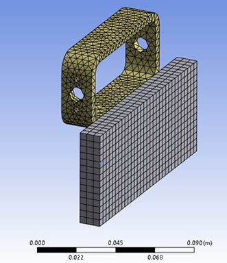

Fig. 7 Fixed Support, Velocity Setup, and Mesh Sizing
We will choose a linear mesh sizing and a default scale due to processing limitations of our equipment. With better equipment we would also refine our mesh more to check convergence for our results.For further iterations of our weapon, our initial conditions will remain the same since whatever redesign we make to our weapon, our weapon radius must remain the same so that we can have good contact on our opponents. Our impact time will be 0.01 seconds. Fig. 8 – 10 show our results in terms of Deformation and then our Von Mises Equivalent Stress for each wall material.

Fig. 8 Total Deformation and Von Mises Stress for a Polyethylene wall
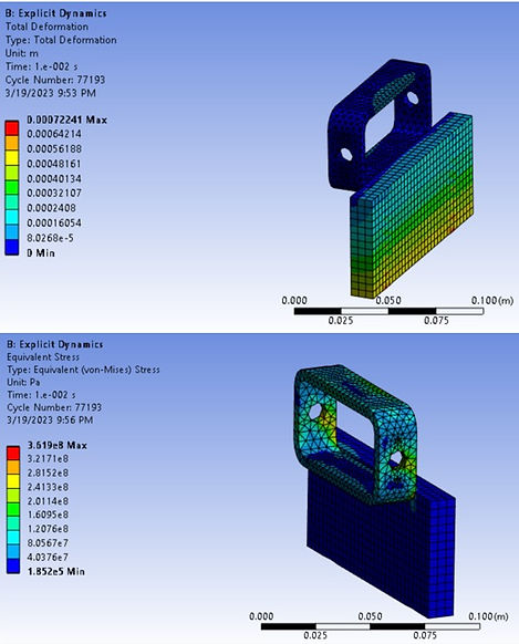
Fig. 9 Total Deformation and Von Mises Stress for an Aluminum wall

Fig. 10 Total Deformation and Von Mises Stress for an Steel wall
Reiteration of Weapon Design
Now we will check our weapon stress in terms of force. Fig 11 shows us the area of the radial stress.

Fig. 11 Weapon shaft and bearing area
Since force is a function of pressure and area, our radial forces along the shaft from our stress analysis are:

Note this is a very simplified calculation and assumes that worst stress seen near the hole is now uniform around the shaft hole instead of localized as depicted in the FEA. Ideally, our redesign would either lower the force or we will choose components that could withstand 15,000 lbf of force. However, we must also balance weight and also the components that we have on hand, specifically a 0.25” diameter shaft. Since 0.5” of steel is on the more extreme end of forces we could possible experience, we try to get a force more on the 1022.94 lbf side of the scale since polyethylene will be the most commonly encountered material. Therefore, we will change the bearings to needle roller bearings which can withstand a much higher radial force and we will thickness of our weapon to increase the areas where we see stress concentrations and better distribute our stresses.


Fig. 12 0.25” side wall and 0.1875” impact wall
Fig. 13 0.25” side wall and 0.25” impact wall


Fig. 14 0.25” side wall and 0.25” impact wall with filleted sides
Fig. 15 0.25” side wall and 0.1875” impact wall with filleted sides
For our next few iterations, we have increased the side walls of our weapon in order to accommodate a 0.25” wide needle roller bearing. Building on top of each iteration, we use fillets to add material to high stress concentrations:
-
We can see in Fig. 12 that by increasing the overall side wall, we now have a stress concentration near the impact point, and our overall stress has increased due to our increase in stiffness due to more material.
-
In Fig, 13, we have increased the impact wall to match the side wall increase, which results ina stress concentration at the same point as our last iteration and near one of the screw holes we need to fasten our pulley.
-
In Fig 14, we have increased material where there was a stress concentration by adding a gradual tangent fillet of 0.5”. We can see that we have gotten rid our our stress concentration and that the maximum stress concentration is below the yield strength of 410 MPa of 4140 steel and 1034 MPa of our Grade 8 alloy steel shaft.
-
In Fig 15. We have reduced the size of our pulley in order to accommodate for weight in other newly redesigned and required components in the rest of the robot. We run our FEM impact analysis and by decreasing the with of the weapon, we have reduced the maximum stress of the weapon to 91MPa and have gotten a much better stress distribution. This will be our final design.

Final design of our Weapon
Final CAD


Fig. 16 Final CAD Models and exploded view of the Wheel, Weapon, and Motor subassemblies
Fig. 16 shows off the final CAD of what we built. Here is a summary of the changes that we made since the prototyping phase:
-
In the weapon, we used needle roller bearings instead of ball bearings since needle roller bearings can support much more structural weight. We also added thrust bearings on either side of the weapon in order to ensure a much more smoother weapon rotation. We also got rid of our original shaft collar design, which we would have used to constrain our weapon and instead opted for a grade 8 alloy steel partially threaded screw and nut design. This is a much stronger steel than what we were using earlier, cheaper to buy due to the rough finish (non issue due to the dead-shaft design), and lighter overall since we got rid of the shaft collars.
-
We used a previously purchased UHMW pulley and turned it on a lathe to create a shaft spacer,
-
We found that the motor clamps sold for our weapon motor were to large to actually clamp the weapon motor. However, these are still good clamps and we need the internal spacing for wires. To rectify this, we created a 3d printed motor face mounting plate using M2.5 and M3 screws, and adjustable screw mounts.
-
Since our front wall is probably not going to get hit, we decided to remove one of our steel through rods to save weight, To constrain the rotating motion of the wall due to this removal, we extended the motor mounting screws to be 2 inches long and pressing into the middle wall. We also added a battery and weapon esc bracket that we 3d printed.
-
We added 0.02 - 0.06" chamfers as well as 0.05 - 0.1" fillets to any interior corners or edges to reduce stress risers.
-
We also got rid of the back plate, the screws for the backplate, and the screws for our interior wheel mounts. We found that 0.5" UHMW back wall is very solid and that a backplate would no longer be needed. The interior wheel mounts are now constrained by a slot in the middle wall.
Manufacturing


Fig. 17 Manufacturing via Water Jet, Heat shrink fitting, Drill Press, Lathe, transfer punch jigs
Structural Manufacturing
In order to manufacture our weapon and structural components, we first converted our part files into .ord files for our school's waterjet, which is the OMAX 2626. We used the waterjet to cut out our weapon and UHMW structural walls and chassis. We created some 3d printed jigs to properly place indents using transfer punches. These would locate the holes for us on the drill press and the lathe.
We purchased some Colbalt drill bits in order to punch through our weapon which was made of 4140 hardened steel. We drill pressed our shaft holes and then tapped the side holes to fasten our pulley to the weapon itself. We used a propane torch to heat up our shaft holes to heat shrink fit our bearings into place. We consulted the ASME Y14.5 Wall chart to find the proper tap hole for every screw hole that needed to be tapped on both the weapon and the UHMW parts. We used a 3 and four chuck lathe for the through holes for the steel rods.
Some things we changed was to remove the wheel fillets. We felt that this didn't give a significant advantage to our robot as the wheel still wasn't fully protected and that it was better idea to just swap out the wheels as they got damaged after each match. We also changed the plate screws to tapping screws for the UHMW.
Electronics Manufacturing
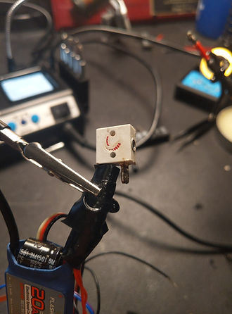


Fig. 18 Soldering Station
This was my first foray into soldering, so the result were not as great as I would have liked. I used a Pinecil soldering iron, some Kester leaded solder, and a tin of rosin flux. One thing I had to do was repair the PCB of the wheel esc's due to the fact that during finagling wires down into the robot, I accidentally ripped the red voltage wire from the pcb itself. To prevent this in the future, After soldering I place a glob of hot glue onto the end of the pcb itself. This way, any forces would be pulling on the pcb instead of the 24 gauge wiring.

Wiring Diagram; Credit to Robobears for drawing this.
Finished Robot Ready for Competition


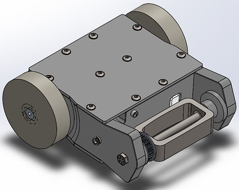
Fig. 19 Finished Robot
This is our finished product. We had to get rid of the left internal support due to a lack of space for wiring. If I could change anything, It would be to use less solder so that our wires could be arranged better.
Fig. 20 Motor Test Video
Here is a video showing our motor test. I place a weapon lock on the weapon for safety reasons, but It can still move up and down to verify the directionality of our motors.


Me, Harin and our finished robot
Driving Practice
Bill of Materials
Here's Links to my BOM Spreadsheets
Credit
Credit to my other teammate Harin, my friend Franky who's workshop I used, to Deborah who helped me figure out 3d printer prototyping, and to Anthony and Wilem of Glitch team, and Nicky and Adit from Robobears (UC Berkeley Combat Robotics) for helping me figure a lot of this out.